Home / Technology
The process
Metal 3D printing from wire.
In wire-based Directed Energy Deposition (DED), an electric arc melts standard welding wire. The system lays bead upon bead and layer upon layer along programmed paths. Instead of removing material or building a mould, the geometry is created directly.
Simplified principle
Layer by layer along the path.
Parts are printed near-net-shape with a machining allowance. Functional, sealing and mating surfaces are then machined to size. This combines the freedom of printing with the precision of conventional machining.
- 1Wire from spool
- 2Torch with shielding gas
- 3Arc and melt pool
- 4Torch follows path
- 5Built up layer by layer
- 6Base plate
Wire as feedstock
Standard welding wire, low- or high-alloy steel depending on requirements. Standardised, available from many manufacturers, not single-source.
Geometry from paths
Path planning defines how the paths build up the part layer by layer. It is our own software.
Near-net-shape, then machined
Parts are printed with an allowance; functional surfaces are brought to size by CNC milling or turning.
What makes WIRED3D different
We build the technology we manufacture with.
WIRED3D is not a contract manufacturer with purchased machines. Our systems, controls and software are the result of several years of research at RWU Ravensburg-Weingarten University of Applied Sciences and process the kind of wire every welding shop has in stock. The result is a process we can adapt ourselves for every component.
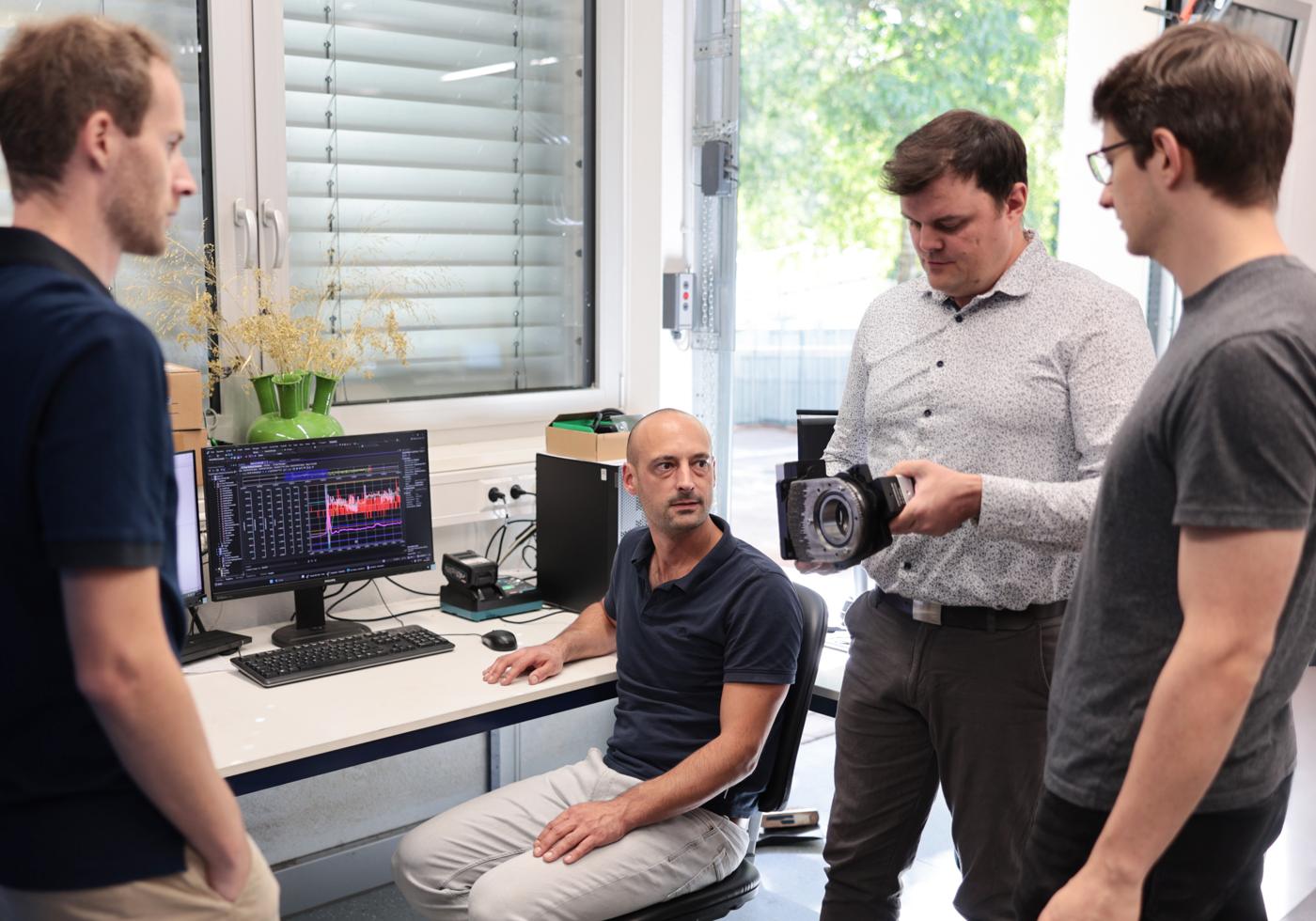
Our own machines
We design and build our systems ourselves. The build volume extends to 1.8 × 2.0 × 1.6 m. Because we know every component, we adapt the process quickly and flexibly to the part. Capacity and know-how stay in-house, with no dependence on machine manufacturers.
Our own digital processes
Path planning, simulation and control are developed in-house. We plan the paths for the specific geometry, check them virtually and monitor the print layer by layer. The result: reproducible components and documented process data for every order.
Rooted in science
WIRED3D emerged from a research group at RWU, received EXIST start-up funding and is part of the ESA Business Incubation Centre. We answer material and process questions with our own test series. Materials and material combinations are qualified, not estimated.
The process chain
From digital to physical part.
Every order goes through the same chain, from your data to final inspection. We develop the software and machines for it ourselves.
- Your dataCAD model or drawing
- Path planningSlicing, paths per layer
- ProgramParameters per material from our own tests
- SimulationVirtual check of the program
- ReleasePreparation of system and base plate
- PrintingDED on our own machine, process data per layer
- InspectionCheck against requirements
- Finished partmachined and documented
Have the part but no documentation? We capture the part with a 3D scan and derive the print model from it, even for discontinued components. The model stays available digitally for the next time it is needed.
Comparison
Wire instead of powder.
How the process differs from laser powder bed fusion and what it is particularly suited to.
| WIRED3D: arc and welding wire | Laser powder bed fusion (L-PBF) | |
|---|---|---|
| Feedstock | Standardised welding wire on spools, available from many manufacturers (no single sourcing) | Specially atomised metal powder with a narrow particle size distribution |
| Material certification | Classified to welding standards (e.g. DIN EN ISO 14341), with material certificate | Powder quality checked per batch: particle size, flowability, moisture |
| Material costs | Price level of commercially available welding consumables | Usually several times higher per kilogram |
| Component size | Up to 1.8 × 2.0 × 1.6 m | Build volumes usually under 0.5 m edge length |
| Deposition rate | Typically 1 to 4 kg per hour | Usually well below 1 kg per hour |
| Handling | No loose powder, no explosion protection; all of the wire ends up in the component | Sieve, recondition and safely store residual powder |
| Strengths | Large, robust parts; printed near-net-shape, functional surfaces machined | Small, delicate parts, fine lattices, smoother surface |
Guide values per process, depending on material, geometry and system.
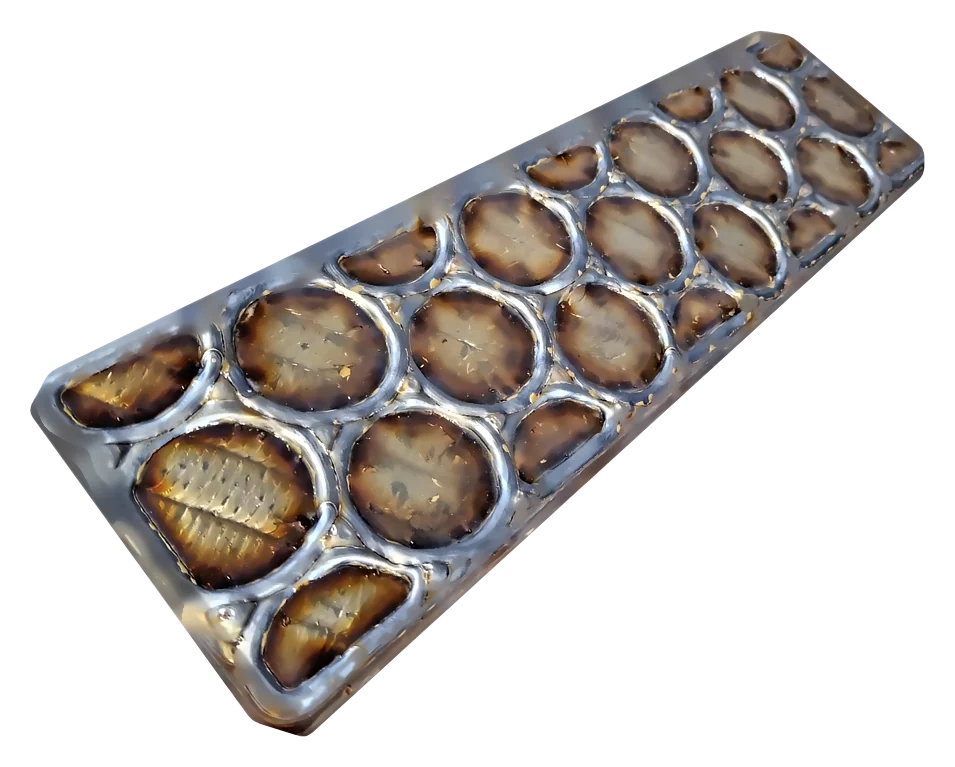
Functional integration & multi-material
Properties that conventional methods can't deliver.
Because we can switch wire during printing and plan paths freely, a part can gain properties that casting, forging or milling cannot produce.
Local wear layers
Hard zones exactly where abrasion occurs.
Two steels in one part
Ductile core, hard shell, from a single printing process.
Integrated channels
Cooling and fluid channels are printed in directly.
Bionic design
Topology-optimised structures that follow the load path.
Start with the Innovation Check
One part. One question. One sensible next step.
Let's find out together whether additive metal manufacturing adds real value to your part. Free of charge and confidential.